Testing the DS1307 Real-time Clock with Bus Pirate
A while ago I came up with a project for a simple desk clock. It is one where I used a small 20 pin DIP IC microcontroller, the Atmel AT89C2051, that is a modernized version of the Intel MCS-51. It includes 2k of flash memory for program storage.
For my project, I wrote a C program that allowed it to function with a 4 digit 7 segment display and some buttons to work as a desk clock. The program was compiled using SDCC and then the chip was programmed using a Xeltec chip programmer.
I created a circuit board using EagleCAD and sent the files to a board manufacturer to get a few sample boards created.
The accuracy of time was not very good, given it was just using interrupts from a crystal resonator. I decided to include the DS1307 to have a more accurate time source. To use the DS1307 with the AT89C2051 I would use C to “bit bang” communications to and from the I2C bus. In order for this to work, I needed to get the communications patterns worked out. For this, the Bus Pirate was a great fit and a low-cost option for learning and testing I2C.
Bus Pirate Overview
The Bus Pirate is a project from Dangerous Prototypes that is sold through a number of distributors. I think this small device offers a lot of power when it comes to solving problems with communicating with serial bus devices. I’ve used it to debug issues with addressing of devices and validate communication details.
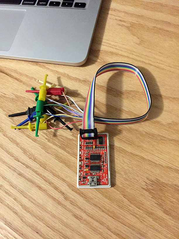
There are 2 good tutorials that are available on the Dangerous Prototypes site. After going through these its pretty easy to understand using the Bus Pirate for I2C and SPI bus interfaces. The only thing I wasn’t able to get is the 3eprom board. So I ended up making my own, first on a breadboard, then I hand wired one.
DS1307 Overview
The DS1307 is a small real-time clock and calendar that can be used with a microcontroller to accurately track the time and date. A CPU communicates with the DS1307 through I2C, a commonly used serial bus. The DS1707 features a small package size and low power operation.
Bus Pirate Setup
After the bus pirate leads are connected to the DS1307, the bus pirate is configured for I2C mode. In this configuration, the bus pirate pull-up resistors are used. The DS1307 is setup on a breadboard with minimal connections.
From the menu, enter m to set the mode, then select I2C by entering 4.
Using the lower speed, choose 1 for 5KHz.
HiZ>m
1. HiZ
2. 1-WIRE
3. UART
4. I2C
5. SPI
6. JTAG
7. RAW2WIRE
8. RAW3WIRE
9. PC KEYBOARD
10. LCD
(1) >4
Mode selected
Set speed:
 1. ~5KHz
 2. ~50KHz
 3. ~100KHz
 4. ~400KHz
(1) >1
READY
I2C>
At this point, the bus pirate is ready to communicate with devices on the bus. In order to use the DS1307 setup on the prototype board, the pull-up resistors from the Bus Pirate are engaged.
The W command powers the bus. p selects the pull-up resistor options. In this case, I choose 2 to enable them.
I2C>W
POWER SUPPLIES ON
I2C>p
 1. Pull-ups off
 2. Pull-ups on
(1) >2
Pull-up resistors ON
I2C>
I2C Address Discovery
The next thing to do is to search to see what addresses are responding on the bus. This is optional if you know the addresses of the device, but I found this helpful in other projects as a way to confirm the address configuration. It also tells you the device is responding on the bus.
Bus Pirate has a macro to search for addresses. To start that, enter 0 to get the macro menu. Next select 1 for address search. The macro will run and print the device addresses it locates. In this case, just the one device as it is the only one connected.
I2C>(0)
 0.Macro menu
 1.7bit address search
 2.I2C sniffer
I2C>1
WRITE: 0x01 NACK
I2C>(0)
 0.Macro menu
 1.7bit address search
 2.I2C sniffer
I2C>(1)
Searching 7bit I2C address space.
   Found devices at:
0xD0(0x68 W) 0xD1(0x68 R)
I2C>
So the addresses are 0xD0 and 0xD1 in hex. In Binary, that is 1101 0000 and 1101 0001.
The 0x68 is the hex address of the device. Read and write are accomplished by shifting the bits left and putting a 1 or a 0 on the end of the address to determine read or write respectively.
Read and Write Access of the DS1307
So first, lets read 3 registers using the address 0xD1 or in binary 11010001.
I2C requires start and stop bits, these are sent from the Bus Pirate using left [ and right ] brackets. To read 3 bytes, we use r:3.
If you refer to the DS1307 data sheet, this reads the seconds, minutes and hours registers.
This is repeated a few times to show that the register values are changing.
Read the DS1307 data sheet. It has very specific details on how the device works when reading and writing. It is similar to many of the I2C devices I have used since.
Typically, you first write to the device to give it a starting register address. Then you read or write to the device to access the register. For the DS1307, after writing the register address, subsequent reads will increment the register address. This means that you can read the time (seconds, minutes, hours, day, date, month, year) by setting the register pointer to 00 and then sequentially reading 7 bytes (0x00 to 0x06).
I2C>[0b11010001 r:3]
I2C START BIT
WRITE: 0xD1 ACK
READ 0x03 BYTES:
0x01 ACK 0x01 ACK 0x01 NACK
I2C STOP BIT
I2C>[0b11010001 r:3]
I2C START BIT
WRITE: 0xD1 ACK
READ 0x03 BYTES:
0x00 ACK 0x03 ACK 0x09 NACK
I2C STOP BIT
I2C>[0b11010001 r:3]
I2C START BIT
WRITE: 0xD1 ACK
READ 0x03 BYTES:
0x00 ACK 0x8C ACK 0x81 NACK
I2C STOP BIT
I2C>[0b11010001 r:3]
I2C START BIT
WRITE: 0xD1 ACK
READ 0x03 BYTES:
0x01 ACK 0x0A ACK 0x01 NACK
I2C STOP BIT
I2C>[0b11010001 r:3]
I2C START BIT
WRITE: 0xD1 ACK
READ 0x03 BYTES:
0x00 ACK 0x08 ACK 0x18 NACK
I2C STOP BIT
I2C>
Now test setting the register pointer to 0x00 before reading and repeating.
I2C>[0b11010000 0]
I2C START BIT
WRITE: 0xD0 ACK
WRITE: 0x00 ACK
I2C STOP BIT
I2C>[0b11010001 r:3]
I2C START BIT
WRITE: 0xD1 ACK
READ 0x03 BYTES:
0x80 ACK 0x00 ACK 0x00 NACK
I2C STOP BIT
I2C>[0b11010000 0]
I2C START BIT
WRITE: 0xD0 ACK
WRITE: 0x00 ACK
I2C STOP BIT
I2C>[0b11010001 r:3]
I2C START BIT
WRITE: 0xD1 ACK
READ 0x03 BYTES:
0x80 ACK 0x00 ACK 0x00 NACK
I2C STOP BIT
I2C>
Summary
In this test, the values are not incrementing. The test DS1307 is only connected to the I2C bus. So it should be possible to write some values and read them back. But the time will not function correctly until a crystal is connected. I’m leaving that for a future test. For now, I have what I need to begin adding this to my desk clock project.
I highly recommend getting the 3EEPROM explorer board or doing like I did and setting one up on e a breadboard. This board is great for going through the tutorials and with sockets or a breadboard it is easy enough to insert the chips you want to work with.
The Bus Pirate is a great idea and works very well. There are a lot of functions it can perform including converting numbers in binary/decimal/hex.
So far I’ve used the Bus Pirate to learn using the DS1307, resolve address and communication format errors with a custom LCD module and to test out some One Wire devices.