Designing a Case to 3d Print
A project I’ve been working on uses a Raspberry Pi with a prototype expansion board that contains an XBee module and a DS1307 RTC module. I had a temporary case made from a sheet of aluminum, but decided it would be better to have a plastic case. I used the project to learn the process of making something from concept to prototype using a 3D printer.
I’ve downloaded and printed a great case design. OctoPrint is running on a Pi attached to the side of my printer and the case is one I downloaded from Thingverse. But I wanted to have a case with a custom expansion area and I wanted to learn how to create my own designs. I thought this would be a simple enough project, basically just a rectangular platstic box.
After looking at several options for an opensource or low-cost CAD package I decided to use FreeCAD. It is an opensource parametric CAD application that is current. FreeCAD supports the most common operating systems. For my project I am using a MacBook Air and a Windows laptop.
My plan was to draw a case, then output the top half and bottom half in STL format for use in Slic3r. Each half is printed separately.
Slic3r takes the STL output and generates G-code that 3D printers use. For Flash Forge Creator Pro, there is a final step to convert the output to x3g using GPX. x3g is the format that Makerbot printers use.
For my printing, I use Octoprint with the GPX plug-in so I just upload the G-code files directly.
So the workflow uses these applications and printer:
- FreeCAD
- Slic3r
- OctoPrint
- Flash Forge Creator Pro 3D Printer
The first step is to determine some dimensions for the case and the boards it will contain. I was able to find a Raspberry Pi 3 board layout with dimensions of the main components - mount holes and ports.
From there the starting point is to draft the bottom dimensions that will be the bottom case. This includes the outline of the case that gets padded to form the case itself as well as the hole locations to place standoffs for mounting the boards.
I used the Raspberry Pi diagram for measurements. For the prototype board I just measured with calipers to get the size and mount spacing.
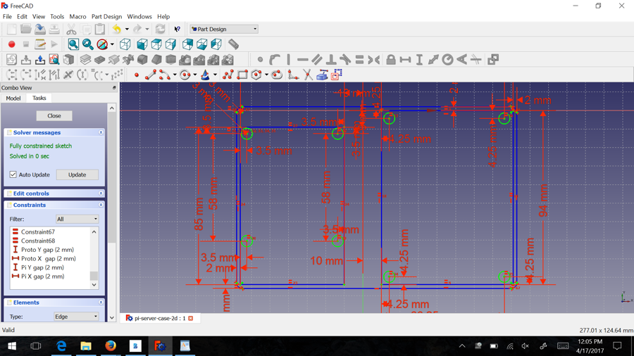
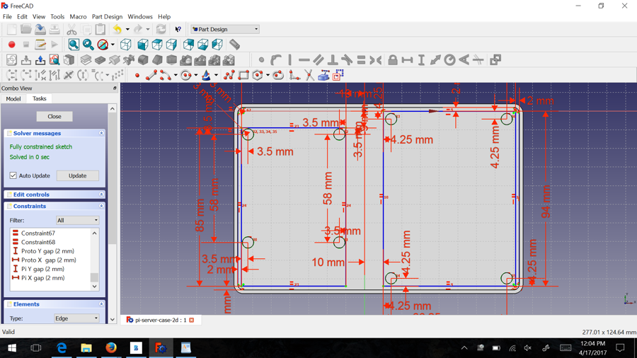
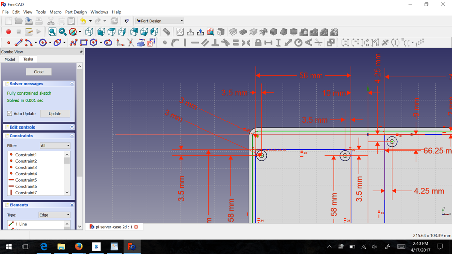
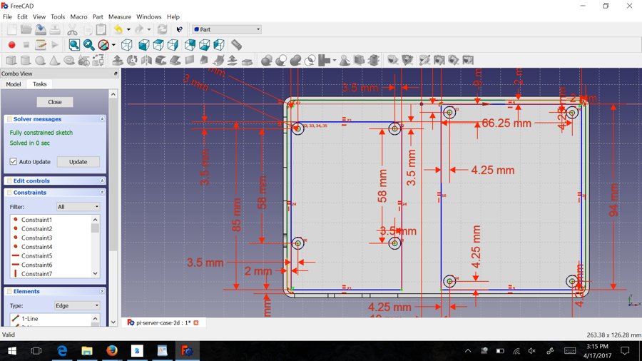
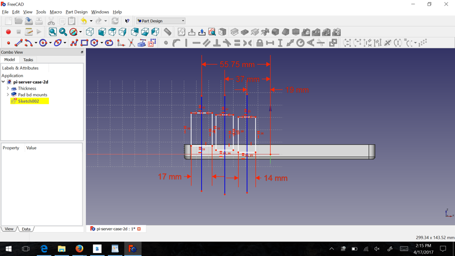
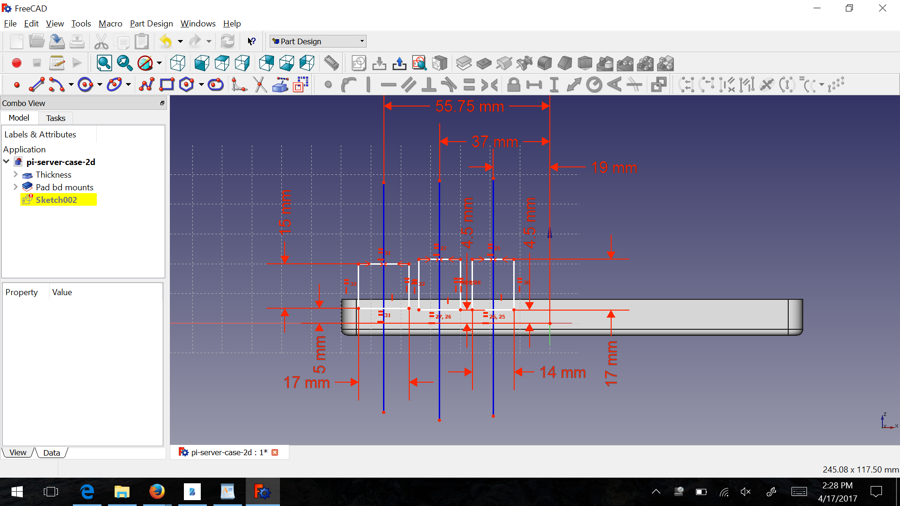
The following screenshots show how it looks in FreeCAD after the dimensions are entered with the drafting workspace. The blue lines are construction lines I entered to show the board placement. The dimension likes are the constraints that are placed on the circles and case edge to create a fully parametric drawing. This allows for modification of some parameters later if needed.
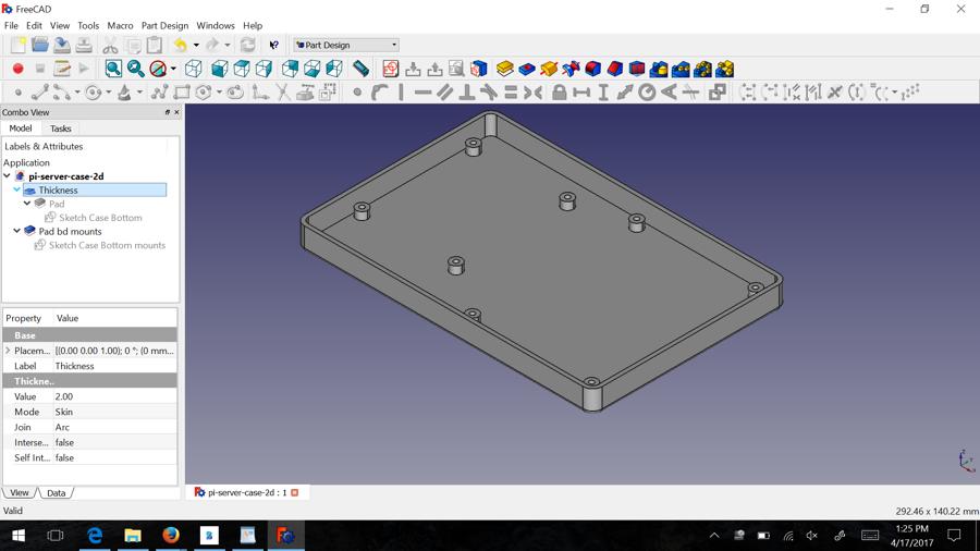
Once the draft is completed, then it is possible to extrude the features. The overall case is a pad with a wall thickness. The board standoffs are pads of circles with a center section removed.
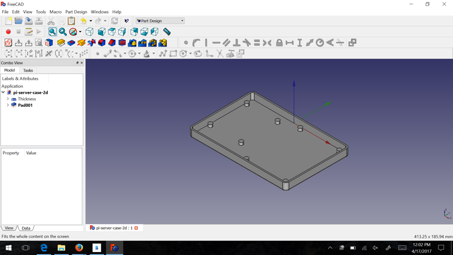
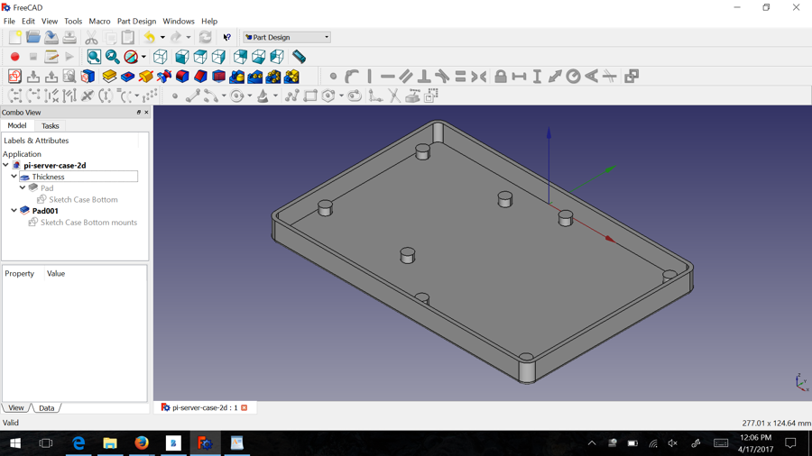
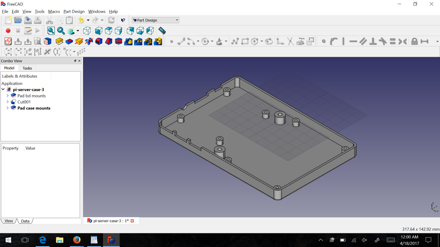
The result is a bottom case with standoffs for the 2 circuit boards.
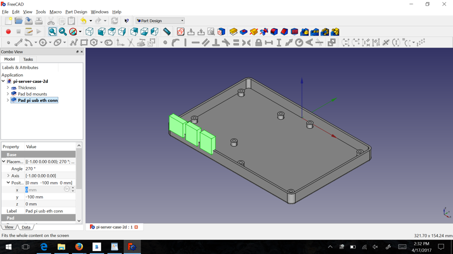
To create the opening for the ports on the Raspberry Pi, I created an outline shape of the port and constrained it to a horizontal line to be able to adjust the location and size. I used 3 construction lines so I could shift the position of the ports easily.
The rectangle shapes are padded and the pad is subtracted from the case to create the ports.
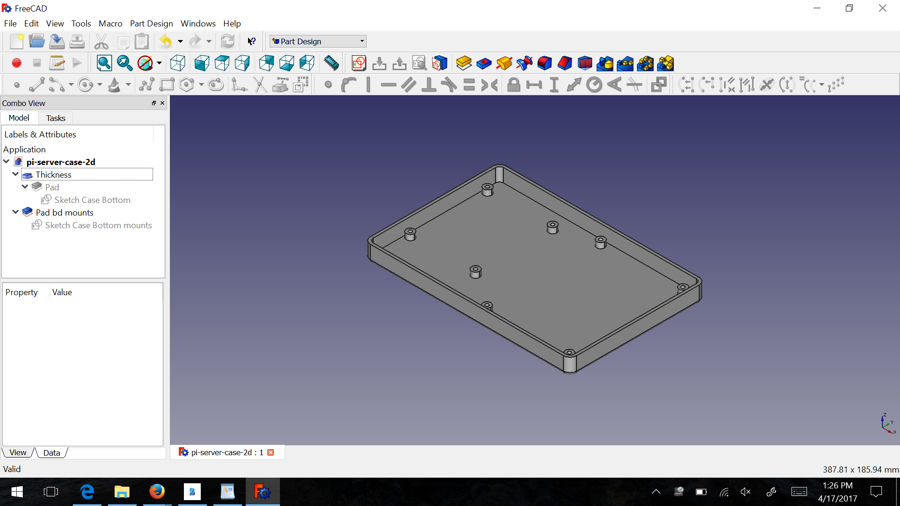
I also added two center mounts to connect the top and bottom case together. Its not the best option with 3d printing because any warping in the print will mean the cases won’t like up exactly. A better way is to use mounts in all 4 corners. I decided not to because the Pi takes up one corner.
After exporting the bottom case STL I used slic3r to check and generate the G-code. When exporting from FreeCAD I just selected the part I wanted to export. That allowed me to export the bottom case from the file first and then export the top of the case separately.
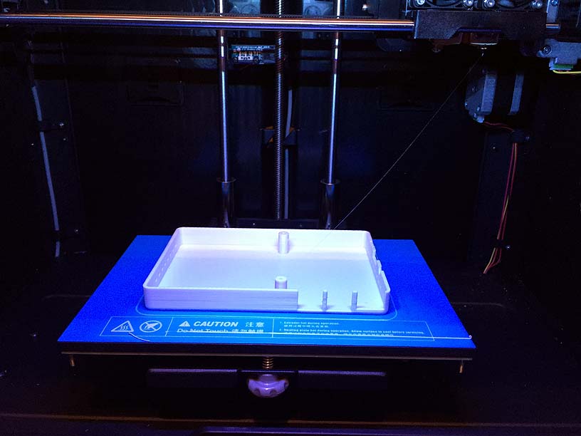
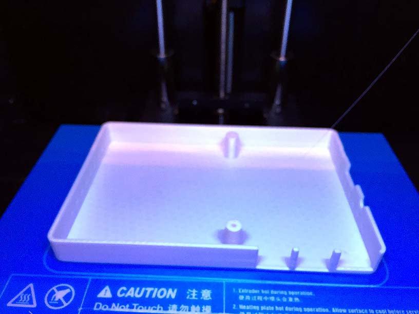
The case print shown here is the top case. I added some air vent holes on the left and right side. I wanted to add a logo and some different shapes for air vents, but I ran into some issues with my FreeCAD file not subtracting shapes correctly. So I decided to use what I had.
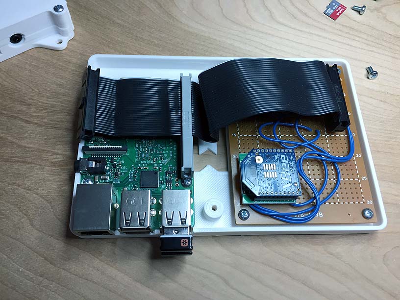
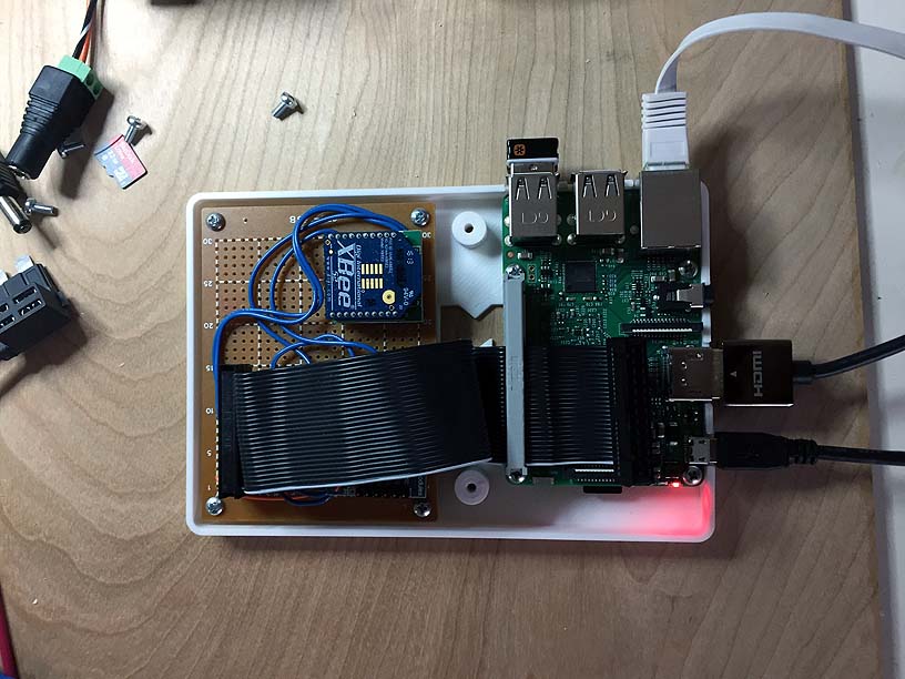
This is the bottom case with the two circuit boards mounted.
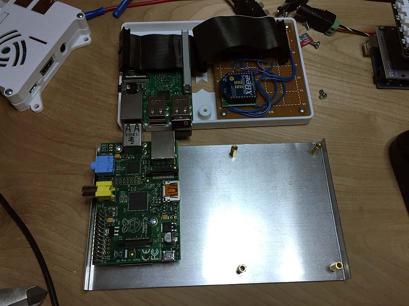
This is a comparison of the 3d printed plastic case and the little aluminum bottom I made using 0.30 sheet aluminum and a mini sheetmetal brake and shear. The brass board mount standoffs were screwed into holes I created with a hand punch.
The bottom case with everything mounted and connected.
In the end I think that overall this works OK. But FreeCAD seemed to have some peculiaraties in how it worked and I was thinking next time I would start over maybe using the existing draft. I would still like to get a logo created on the front and either more vents or a different style of air vent.
For now this system is working great in the new case. I plan to make more cases for future projects.