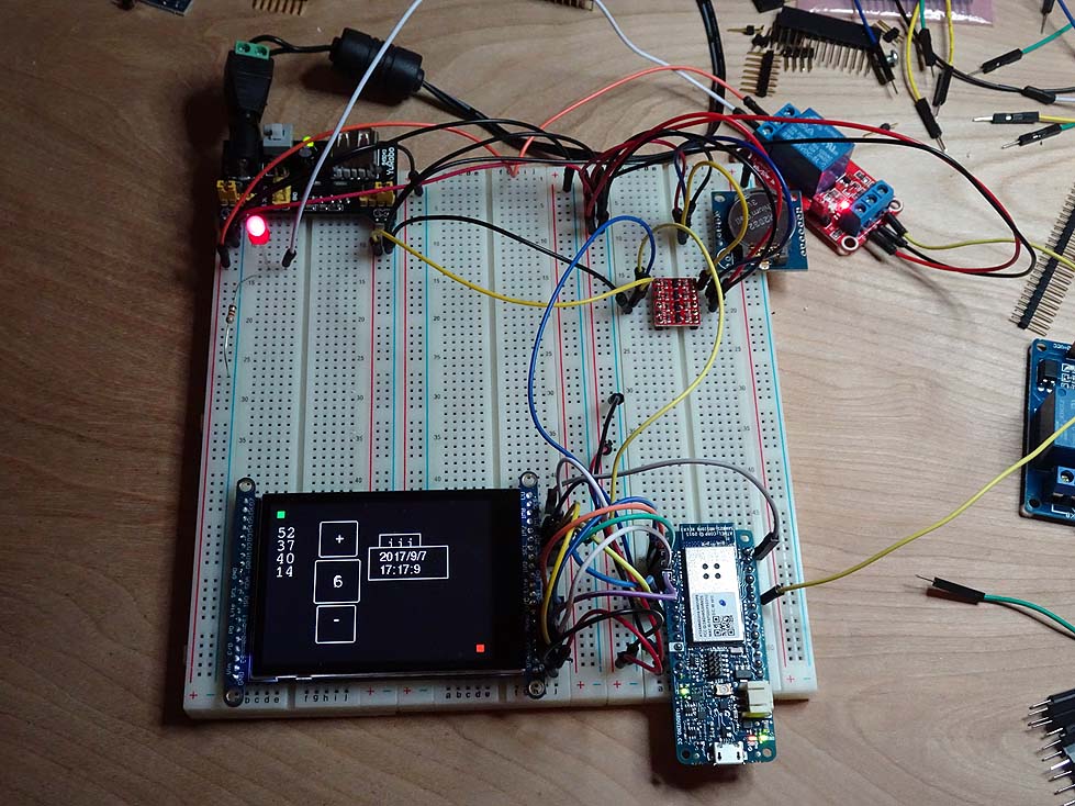
Adafruit TFT and Arduino MKR1000
I recently started looking at graphic displays for projects for use with Arduino. I’ve also been looking at controllers with WiFi for IoT type projects. The first iteration I had is an Adafruit Feather HUZZAH with ESP8266 WiFi using the TFT FeatherWing 2.4” Touchscreen.
This is a simple combination. All that is needed is to solder on the headers and plug them together. Adafruit even provides a nice set of files that can be downloaded and printed on a 3d printer to make an enclosure for them. That was really awesome! It gave me a little dev platform that I could carry with me.
After some initial testing of the feather combination I decided to move to a breadboard with the MKR1000. I wanted larger program capacity while still having the ability to use WiFi. So far the MKR1000 seems like a good fit. I also plan to try out the ESP32 both from Adafruit and from Sparkfun.
The TFT LCD I am using is the 2.8 TFT LCD with a Capacitive Touchscreen. The touch libraries work just a little different from the Feather LCD which is a resistive touchscreen. There are a few other differences like the resistive version has a buffer that needed to be cleared when reading touches and it also provided a pressure reading. The cap touch one seems to work better though.
I used a breadboard for the TFT breakout and the MKR1000 to test drawing buttons and displaying fonts on the screen. The sans version of the font seems to vary significantly between characters so sizing a box for them is a challenge.

In this view I was using the fixed mono font to make it easier to size boxes consistently when the text changes. I also connected a DS1307 module and a relay to test activating it by the touch interface. The display is connected using the SPI pins to save on pin count. The touchscreen controller uses I2C as does the DS1307. The relay is just connected to a digital out pin and an LED to have something easy to turn on and off. There is a test box that shows time and date when the relay is activated just to make it easy to update on screen using the existing buttons I made. So far these are just some test boxes and buttons to work out using the graphics. I am considering making a library to use for buttons and menus. Most of the buttons and text boxes are done. The next part is making a menu system. I have a couple of projects that I want to use these for including a home IoT thermostat.
Hookup is pretty straight forward. Adafruit provides a great doc with instructions and description of using the display with SPI. There is an example that is part of the library, too. The instruction doc uses an Uno. The following table shows the pins needed for connecting a MFR1000 with the Uno pins for comparison.
| UNO pin | MKR1000 pin | LCD Pin |
|---|---|---|
| 5 | Card CS | |
| IM1 to 3Vo pin on LCD | ||
| IM2 to 3Vo pin on LCD | ||
| IM3 to 3Vo pin on LCD | ||
| 12 | SCL | |
| 11 | SDA | |
| D9 | 7 | DC |
| D10 | 6 | CS |
| D11 | 8 | MOSI |
| D12 | 10 | MISO |
| D13 | 9 | CLK |
| Vin to +5V | ||
| GND to ground |
With the TFT breakout connected to the MKR1000, the next part is importing the libraries needed. They are described in the Adafruit learning document for the module. I just added the Adafruit library site in preferences and then used library manager to find the Adafruit libraries and clicked install on the ones I needed.
In the sketch, the include statements for the libraries and configuration I used is as follows:
#include <SPI.h>  // used by tft controller
#include <Wire.h>  // used by touchscreen controller and RTC module


#include <Adafruit_GFX.h>    // Core graphics library
#include <Adafruit_ILI9341.h> // TFT controller library
#include <Fonts/FreeSans12pt7b.h> // font for display
#include <Fonts/FreeSans9pt7b.h> // font for display

#include <Adafruit_FT6206.h> // Touch interface (capacitive)

#include <RTClib.h> // Adafruit rtc fork

// The FT6206 uses hardware I2C (SCL/SDA)
Adafruit_FT6206 ts = Adafruit_FT6206();

// The display uses hardware SPI and these pins
#define TFT_CS 6
#define TFT_DC 7
#define SD_CS 5

Adafruit_ILI9341 tft = Adafruit_ILI9341(TFT_CS, TFT_DC);

// Relay connection
#define RELAY1 0
int relay1State = LOW;

RTC_DS1307 rtc; // adafruit rtc lib
char daysOfTheWeek[7][12] = {"Sunday", "Monday", "Tuesday", "Wednesday", "Thursday", "Friday", "Saturday"};
The defines for the TFT pins are for chip select for the display controller, data/command for the display controller, and the chip select for the SD card. See the examples in the Arduino IDE listed under Adafruit ILI9341 for complete programs.