Using the Adafruit Huzzah32 esp32 Feather with the TFT Touchscreen FeatherWing
I have been using graphic displays for projects for use with Arduino. The first iteration I had was an Adafruit Feather HUZZAH with ESP8266 WiFi using the TFT FeatherWing 2.4” Touchscreen.
It is a simple combination and easy to assemble. All that is needed is to solder on the headers and plug them together. Adafruit even provides a nice set of files that can be downloaded and printed on a 3D printer to make an enclosure for them. That was really awesome! It gave me a little dev platform that I could carry with me.

Using this setup in Mandalay Bay in Las Vegas during a conference, unfortunately the same weekend as the tragedy. Wishing the best for all the families affected.

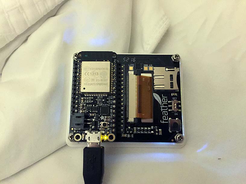
After using on a few trips I decided that I needed more memory for the larger graphic programs. I ordered the newer version of the feather using the ESP32. Adafruit HUZZAH32 ESP32 Feather Board

With the Feather modules, there is a common pinout so it is not necessary to wire anything special up to get it to work with the Feather TFT module. However, the program does need to change to use correct pin mappings.
To locate the pin mappings for the ESP32 module, I just looked at the tutorial for the Feather TFT module. From there it was possible to see what pins were use and where they map to on the Feather HUZZAH32. Then I used the Feather pinout listing to find out which pins to use in software. Feather HUZZAH32 guide pinouts.

One drawback to using the ESP32 is that D0 needs to be pulled low to put it in programming mode. That means that enclosing it completely when doing development isn’t possible because you won’t have access to the button. So I’m using the case back when it is in my bag traveling and just taking it off when I need to upload a program.
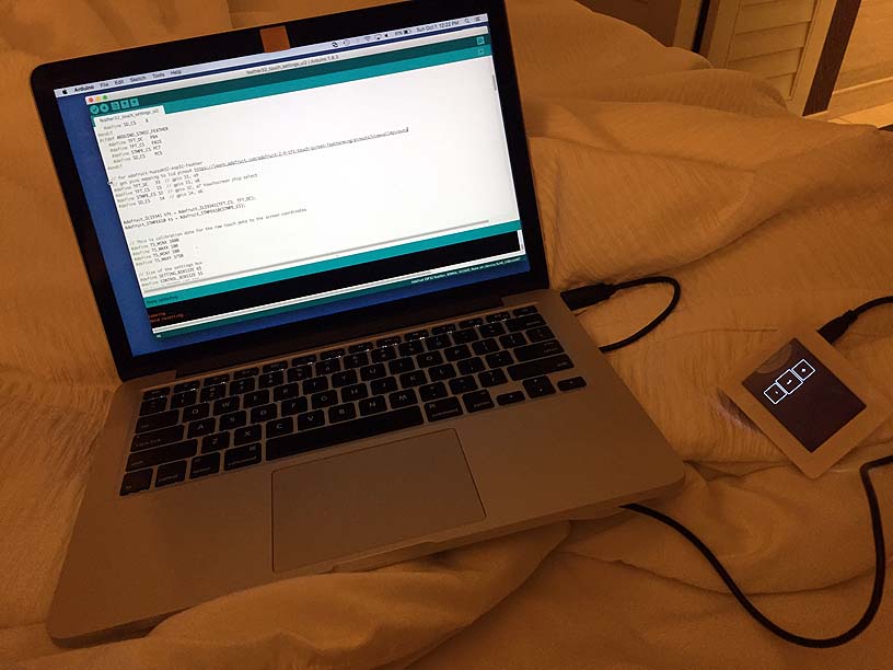
For the Arduino IDE program I used the following pin settings:
#define TFT_DC   33  // gpio 33, a9
#define TFT_CS   15  // gpio 15, a8
#define STMPE_CS 32  // gpio 32, a7 touchscreen chip select
#define SD_CS    14  // gpio 14, a6
I didn’t have to change anything else to get my previous sketches to work with the new processor. So far it all seems to be working well. I’m hoping I can get my graphics routines worked out and in a library to post on GitHub at some point.
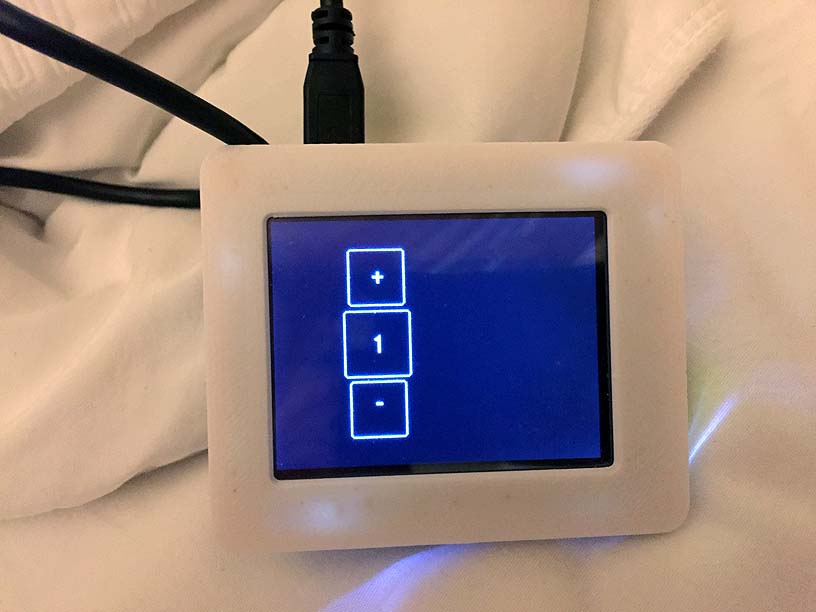
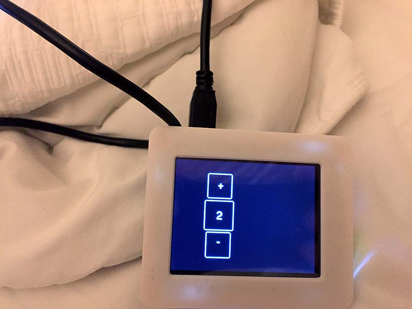
This sketch is a simple graphic screen that draws a couple of buttons and labels them “+” and “-“. Pressing these either increments or decrements the digit displayed.