Sonoff IoT Switch using Mosquitto MQTT and Arduino ESP8266
After acquiring a Sonoff basic WiFi switch I decided it would be a good simple IoT project to get working with Node-RED and the Eclipse Mosquitto MQTT broker. I have a Raspberry Pi server already setup running raspbian so the server part seemed like it would be pretty straight forward.
Part One
I decided that it would be better for me, considering time, to break this into two articles.
Part One, the first article, will get the MQTT server setup and configured. It will also go through communicating with a Sonoff switch. The Sonoff switch is setup with Arduino code and programmed to work with the MQTT server on the same WiFi network.
Part Two will setup Node-RED on the same Raspberry Pi that MQTT is running on. Then Node-RED will be configured to control the Sonoff switch and maybe something typical, such as a lamp.
Starting Configuration - Pi Server
The first step is to get a Raspberry Pi setup with the OS loaded on a microSD card. There are many tutorials for doing this. You will need a USB power supply for the Pi, a monitor, keyboard and mouse.
Raspberry Pi sources:
If you haven’t used a Raspberry Pi before, you will need the following:
- USB keyboard
- USB mouse
- Monitor - HDMI is easiest
- Network - Ethernet cable or WiFi
-
Power supply - USB charger with micro USB cable
Note: It is possible to setup a Raspberry Pi and use it without a keyboard and monitor. If you create an empty file named
sshon the boot filesystem when you put the OS on a microSD card you can locate the IP from the DHCP server (your router) and access the Pi remotely to configure it.
There several ways you can install an operating system on a microSD card for a Pi. I usually download the latest Raspbian image and use a terminal window on my Mac to dd the image to a microSD card.
- Use
diskutil listto locate the device name of the SD card - Unmount the SD card using
diskutil unmountDisk /dev/ - Use dd to write the Raspbian image
WARNING - Make sure you use the SD card device, this overwrites the device!
[showing only the SD card device]
[look for the external device the size of your SD card]

MB-MBA4:raspberryPi mikeb$ diskutil list

/dev/disk4 (external, physical):
   #:                       TYPE NAME                    SIZE       IDENTIFIER
   0:     FDisk_partition_scheme                        *32.0 GB    disk4
   1:             Windows_FAT_32 NO NAME                 32.0 GB    disk4s1

MB-MBA4:~ mikeb$ diskutil unmountDisk /dev/disk4
Unmount of all volumes on disk4 was successful

MB-MBA4:raspberryPi mikeb$ sudo dd bs=1m if=./2016-02-26-raspbian-jessie.img of=/dev/rdisk4
3843+0 records in
3843+0 records out
4029677568 bytes transferred in 50.742503 secs (79414245 bytes/sec)

MB-MBA4:raspberryPi mikeb$ diskutil list
/dev/disk4 (external, physical):
   #:                       TYPE NAME                    SIZE       IDENTIFIER
   0:     FDisk_partition_scheme                        *32.0 GB    disk4
   1:             Windows_FAT_32 boot                    58.7 MB    disk4s1
   2:                      Linux                         4.3 GB     disk4s2
MB-MBA4:raspberryPi mikeb$
There are other options including purchasing a pre-loaded SD card.
There is a documentation page here that describes installation from common operating systems.
After the Pi boots, some basic configuration is required. Then it will need to have the software updates installed. If your Pi isn’t new, its likely that it will also need firmware updates.
Some additional tasks you may want to do.
- Setup ssh access
- Create additional accounts and set passwords
Installing MQTT Software
Once your Pi is setup, the next thing to do is install the mosquitto MQTT software packages.
Installing Packages
Use the following syntax to install the packages.
sudo apt-get install -y mosquitto mosquitto-clients
The mosquitto web site has information on its use and configuration. There is also a list of distributions and instructions for other operating systems.
Other options to get mosquitto mqtt
Configure MQTT
The mosquitto configuration file needs to be setup before using it with the ESP8266 arduino mqtt library. The default installation allows anonymous access. If it is your home and you are the only one using it, then you can choose to test without passwords. It is highly recommended to configure a more secure access method. I chose to use password for access control.
Mosquitto uses an /etc/conf.d/ directory to allow multiple configuration files. This makes it easy to just copy the configuration to a new file. In my case I called it mb2018.conf. The configuration disables anonymous access and sets the location of the password file.
Example basic configuration file:
/etc/mosquitto/conf.d/mb2018.conf
# mosquitto configuration
# 2018-feb-09
# copy to /etc/mosquitto/conf.d/mb2018.conf
allow_anonymous false
password_file /etc/mosquitto/passwd
Users are added with the mosquitto_passwd command. Use it to create the password file for the first user with the -c flag. After that the -c flag is no longer used.
sudo mosquitto_passwd -c /etc/mosquitto/passwd <user_name>
Note: The -c is used to create the password file. It should only be used for the first user created. Additional users can be added to the same file by omitting the -c.
Example of creating a sonoff user:
sudo mosquitto_passwd /etc/mosquitto/passwd sonusr1
password xyz123abc
After the password file is setup and populated with at users, restart the mosquitto server so the new settings take effect.
sudo systemctl restart mosquitto
Check the status using:
systemctl status mosquitto
pi@mb-pisvr1:~ $ systemctl status mosquitto
● mosquitto.service - Mosquitto MQTT Broker
   Loaded: loaded (/lib/systemd/system/mosquitto.service; enabled)
   Active: active (running) since Tue 2018-12-18 20:25:30 EST; 2 months 19 days ago
     Docs: man:mosquitto(8)
           https://mosquitto.org/
 Main PID: 13499 (mosquitto)
   CGroup: /system.slice/mosquitto.service
           └─13499 /usr/sbin/mosquitto -c /etc/mosquitto/mosquitto.conf
Testing MQTT Locally on the Pi
You can use the command line utilities of the mosquitto MQTT server to send and receive messages.
Use the following syntax to listen for messages:
mosquitto_sub -v -t sonoff/node01/cmd -u sonusr1 -P xyz123abc
Open another terminal and use the following syntax to send messages:
mosquitto_pub -t sonoff/node01/cmd -u sonusr1 -P xyz123abc -m "0"
First open two terminal windows to the Pi. In the first window enter the command to listen to messages sent, mosquitto_sub using the above syntax to specify the topic, user and and password.
Next, in the second terminal window, use the command to send messages to the queue, mosquitto_pub. When you see the messages, you know the configuration for mosquitto is working OK.
pi@mb-pisvr1:~ $ mosquitto_pub -t sonoff/node01/cmd -u sonusr1 -P xyz123abc -m "0"
pi@mb-pisvr1:~ $ mosquitto_pub -t sonoff/node01/cmd -u sonusr1 -P xyz123abc -m "1"
On the terminal that is listening to the queue you will see the following output.
pi@mb-pisvr1:~ $ mosquitto_sub -v -t sonoff/node01/cmd -u sonusr1 -P xyz123abc
sonoff/node01/cmd 0
sonoff/node01/cmd 1
MQTT uses topics to organize messages that are published. This allows a client to subscribe (read) or publish (write) messages in a hierarchy that makes it easy to have a large number of clients.
Topics can be organized in a directory style format using “/” as a separator. A client that wants to listen to messages can use the specific topic. It can also use wild cards to listen to messages published to several topics.
The mosquitto server also provides a list of system topics using the $SYS hierarchy.
For more info see the mosquitto man page. The sections titled Broker Status and Wildcard Topic Subscriptions have the details.
Additional commands
Finding the version of mosquitto
mosquitto_sub -v -t \$SYS/broker/version -u sonusr1 -P xyz123abc
Setup the Sonoff Switch
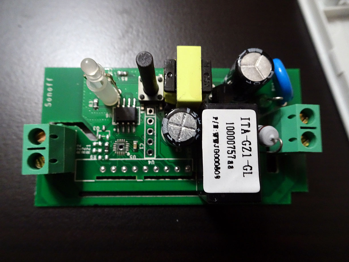
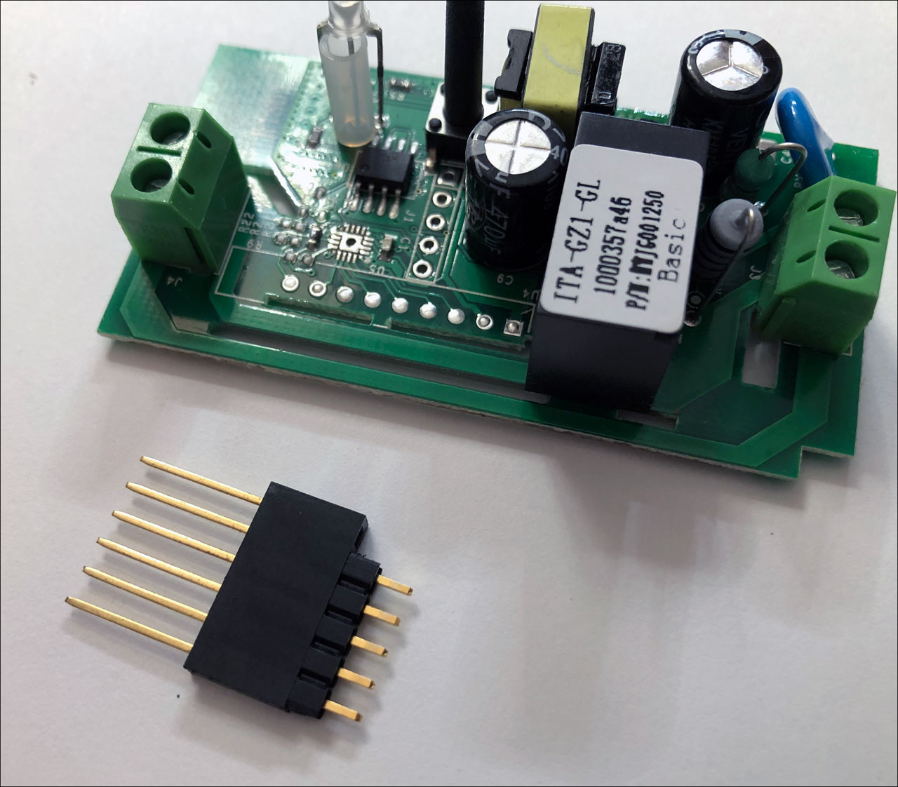
The Sonoff switches do not come with programming headers. The first thing you will need to do is solder on a header. Once that is complete, connect a USB serial TTL cable to upload programs to the ESP on the Sonoff board.


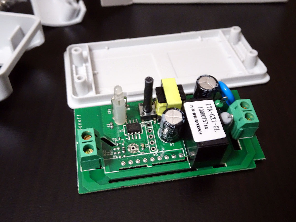
Remove the end caps that cover the terminal blocks.
The bottom of the case can easily be removed with a small screwdriver. Cut the tag that is used to seal the bottom if there is one. Then pry open the edges at the bottom.
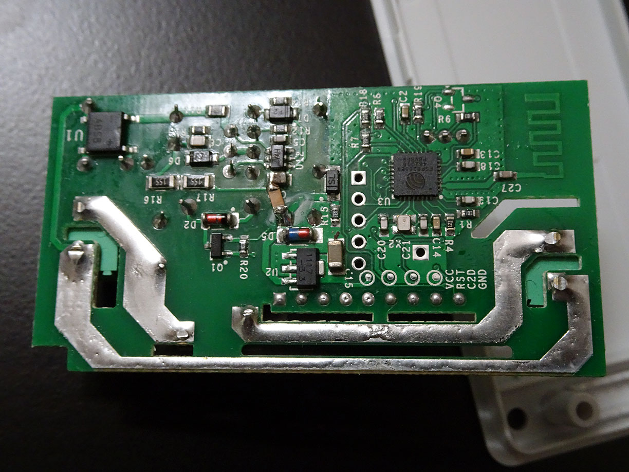
Once the bottom is open lay the case aside. You will need to solder on a header to attach the programming cable.
From the bottom it is easy to see pin 1 which is the square pad. There are 5 pins on the header. Only the first 4 pins are required for programming.
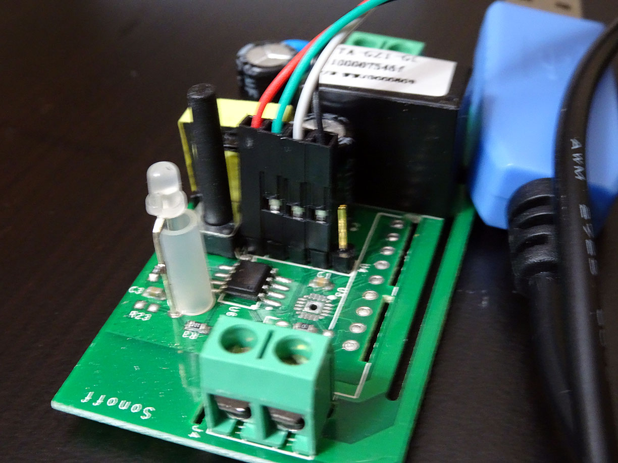
Connecting the Programming Cable
I used an Adafruit USB TTL console cable. The cable connects as follows:
Adafruit USB to TTL console cable
| Sonoff J1 | USB TTL | Description |
|---|---|---|
| VCC | Red | VCC |
| RX | Green | TX |
| TX | White | RX |
| GND | Black | GND |
Be sure to check the Adafruit product page for links to the driver needed for the SiLabs CP2012 chipset. If this is the first time you are using this cable it will require having the driver installed.
Tip: When soldering the header on the circuit board, I think it helps to take one of the arduino stacking headers and use it to give some extra length to the header pins I solder. It gives enough length so that the pins push between the table and the circuit board to get the header positioned best for soldering.
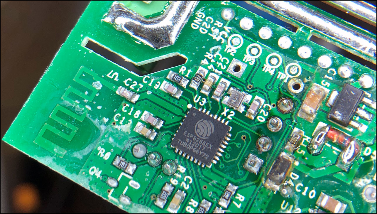
Setup Arduino IDE for ESP8266
You will need to install the packages to program the ESP on the Sonoff switch. In older releases it was more complex. Now there is an online package distribution where you can use the Arduino IDE board manager to install the files needed.
Install the ESP Board for the Arduino IDE
The following site has instructions for using the ESP8266 Arduino Core.
Install the ESP8266 board files in Arduino.
The steps from the link above show you how to add the library location to the board manager URLs in preferences.
http://arduino.esp8266.com/stable/package_esp8266com_index.json
Then in boards manager locate and install the ESP8266. After its installed, select the ESP8266 from the boards manager.
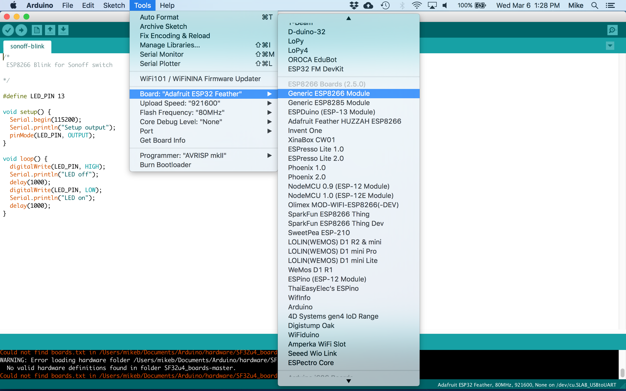
The following screenshot shows the settings to configure for the board.
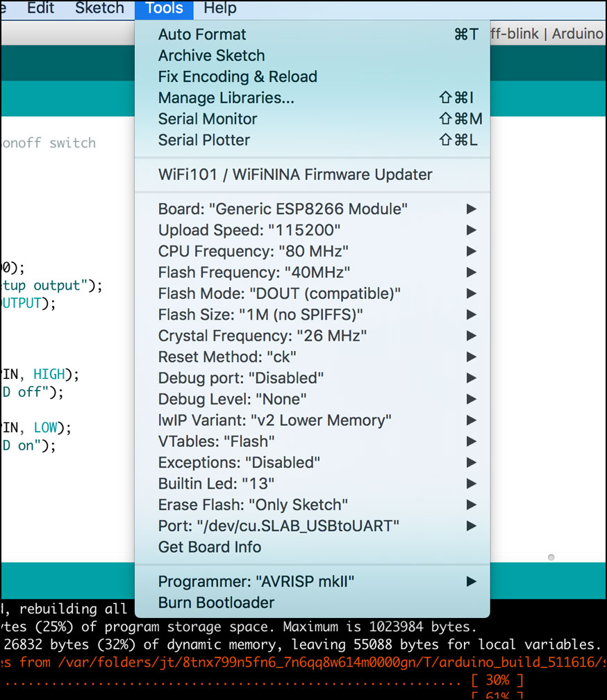
These are the settings I used. I used the defaults for the other settings.
| Setting | Value |
|---|---|
| Board | Generic ESP8266 Module |
| Upload Speed | 115200 |
| CPU Frequency | 80 MHz |
| Flash Mode | DOUT |
| Flash Size | 1M (no SPIFFS) |
| CPU Frequency | 80 MHz |
| Crystal Frequency | 26 MHz |
| Reset Method | ck |
| Debug port | Disabled |
| Debug Level | None |
| IwIP Variant | v2 Lower Memory |
| VTables | Flash |
| Builtin Led | 13 |
| Port | the port specified with USB serial connection |
Configuration details
Mac
| Description | Version |
|---|---|
| Arduino IDE for Mac | 1.8.8 |
| esp8266 by ESP8266 Community | 2.5.0 |
| PubSubClient by Nick O’Leary | 2.7.0 |
| MacOS | 10.12.6 |
Windows 10
| Description | Version |
|---|---|
| Arduino IDE for Windows 10 | 1.8.8 |
| esp8266 by ESP8266 Community | 2.5.0-beta1 |
| PubSubClient by Nick O’Leary | 2.7.0 |
| Windows 10 Home | 10.0.17763 |
| Dell XPS 2 in 1 | XPS 13 9365 |
Note: There are a various versions of Sonoff switches, Arduino IDE and the ESP8266 board files. The above table is provided to help show a combination that was tested to work together.
Configure ESP8266 Board in the Arduino IDE
- Set the device settings in the IDE
- Upload a test program
In order to upload a sketch to the Sonoff, you must press and hold the switch (there is only one) while the device is powered on. I press the switch and then plug the USB connection to my laptop, then after a short delay I release the switch. That enables programming mode.
One its connected and powered on, you select the port in the Arduino IDE. Then you can upload a sketch. Open the serial port monitor to see any serial print statements in the sketch.
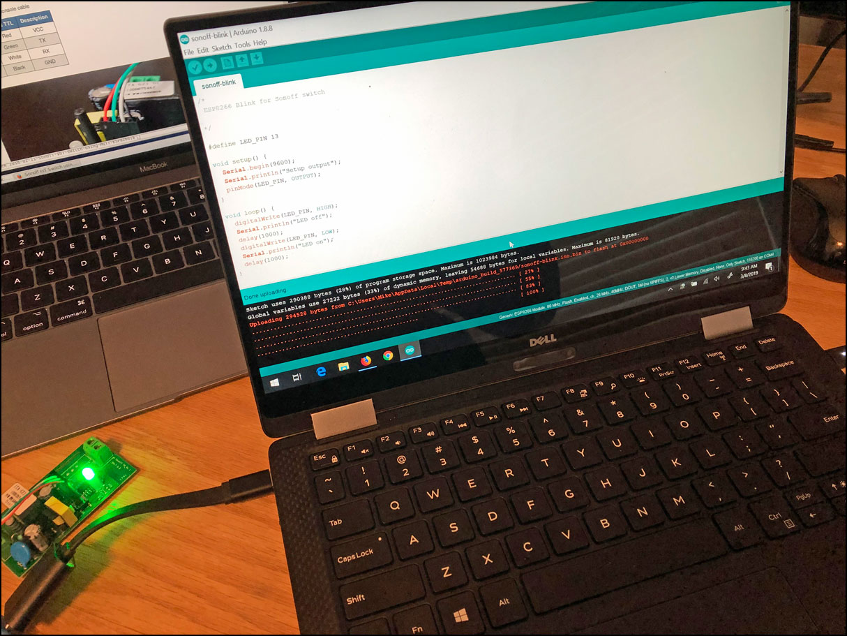
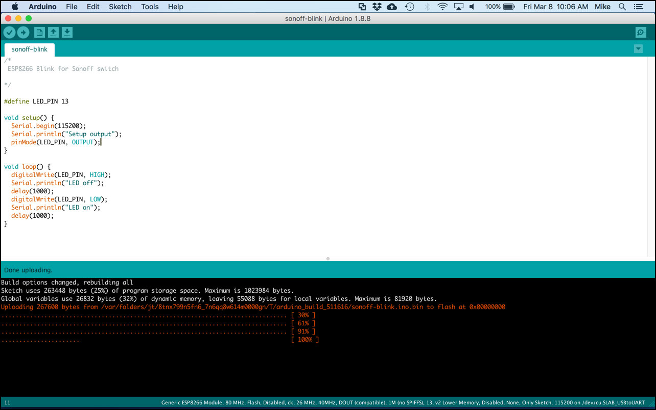
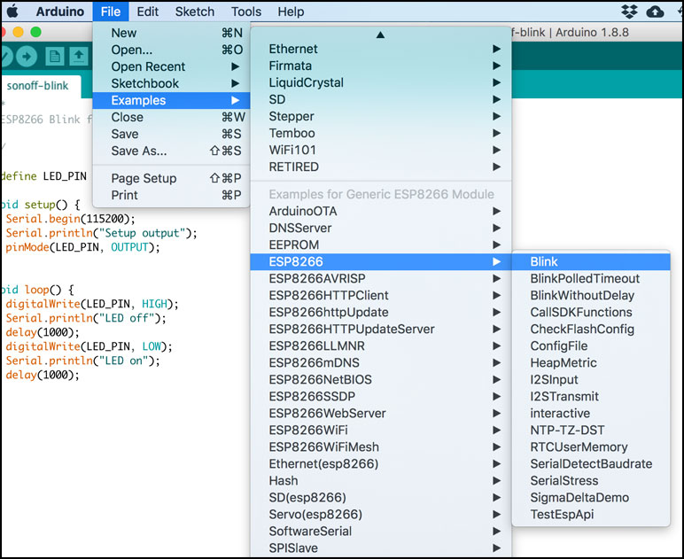
The following sketch is a simple blink to test that you have all the settings correct for programming the ESP on the Sonoff. There is also a generic blink example. The only difference is the generic one uses the pin defined for the LED and this example sets it specifically to pin 13 so its correct for the Sonoff.
/*
Generic ESP8266 module, Blink test for Sonoff switch

*/

#define LED_PIN 13

void setup() {
  Serial.begin(115200);
  Serial.println("Setup output");
  pinMode(LED_PIN, OUTPUT);
}

void loop() {
  digitalWrite(LED_PIN, HIGH);
  Serial.println("LED off");
  delay(1000);
  digitalWrite(LED_PIN, LOW);
  Serial.println("LED on");
  delay(1000);
}
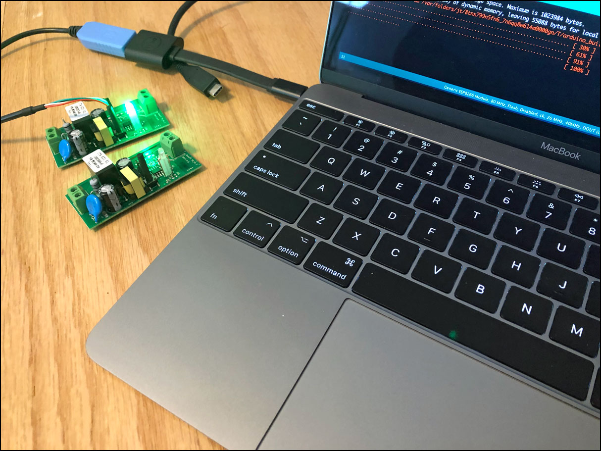
Once the sketch is entered and the board settings are done, upload the sketch to a Sonoff switch. The sketch will compile and then start to transfer to the switch. The following shows how a normal upload should look. It should progress to 100%.
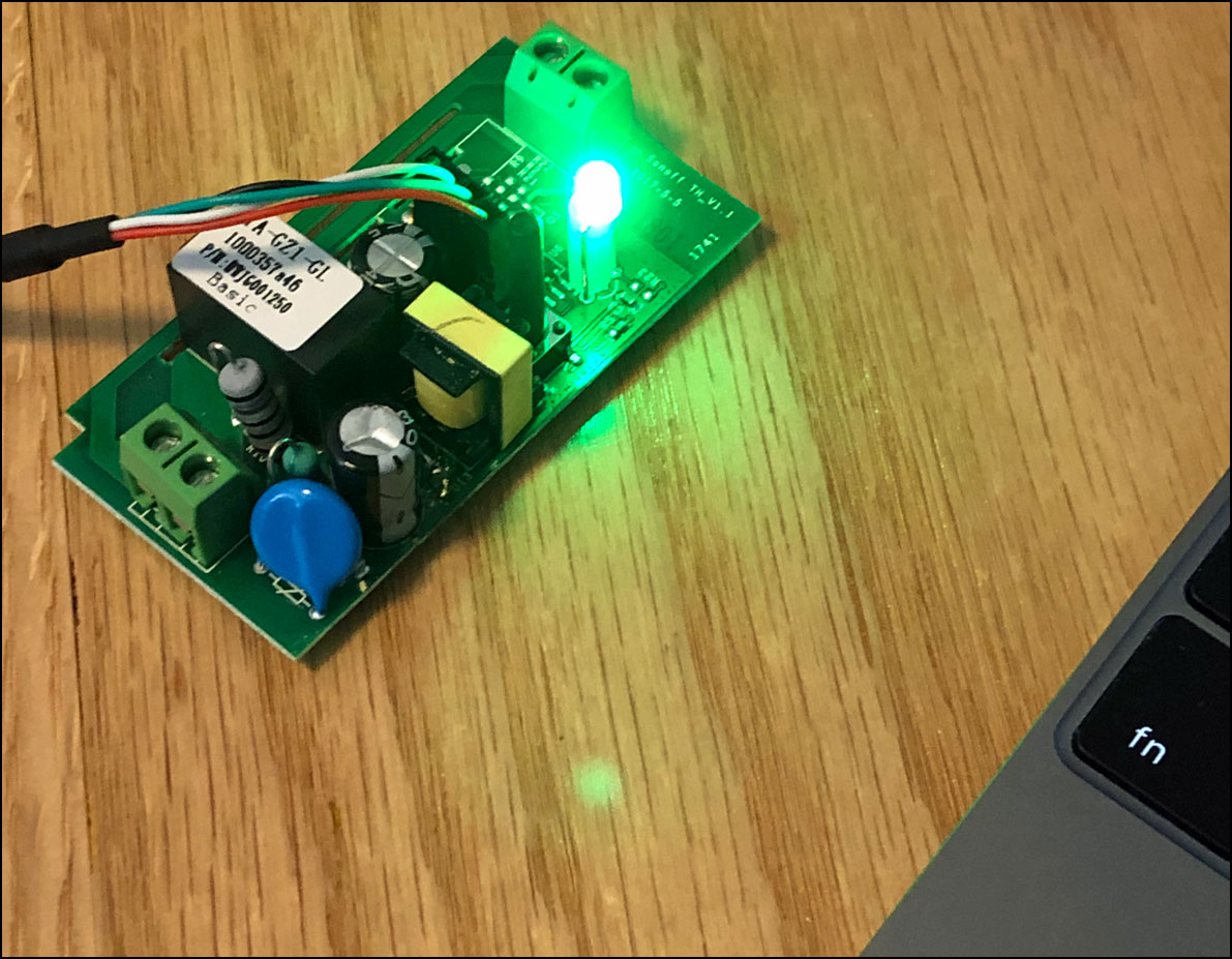
After the upload completes, the switch should reset and run the program. At this point you should have a switch with a blinking LED. If you open the serial monitor you should see messages for LED on and LED off.
If you encounter problems getting the blink sketch to work it is best to look at where the issues are. With one switch I had errors that it would not connect to upload a sketch. The switch was dead and wasn’t working. When I used a new switch it worked OK.
You can also have problems with changes in hardware with different switch models. If you are able to upload successfully but the LED doesn’t blink, then check settings to see if the hardware you have needs different settings.
You can also use the blink example from the library if you prefer. The examples are a great way to start a sketch or to run a quick test of new settings.
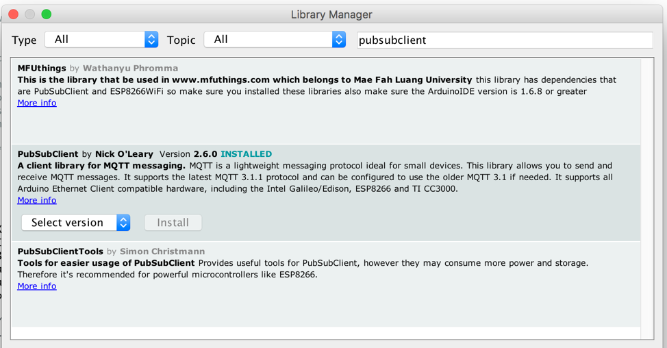
Install the Arduino MQTT Library
In order to talk to the MQTT server, the Sonoff switch will need a library. The library I chose is called PubSubClient.
Using the Library Manager search for and install the library. The Library is called PubSubClient by Nick O’Leary. Install the latest version.
Switch Program
Overview
I decided to use the first switch to control a desk lamp. I bought a lamp at Target and cut the power cord close to the base. I connected the power cord to the Sonoff switch. I attached the switch to the lamp base using adhesive backed velcro so that I could remove it easily.
Features
- LED light is on when the switch is on
- Switch button controls the light
- Turn on or off from MQTT commands
- Sends status after connecting to MQTT
- Send status when switch pressed
Future features
- Change LED light to blink if unable to connect
- Flash once if WiFi connection is down
- Flash twice if MQTT connection is down
- Configure for over the air updates
- Use ethernet MAC as node ID
- Automate settings to support more switches easily
Switch Sketch
I published the settings and sketches on here on Github.
Make sure to change the WiFi SSID and password. You also need to set either the IP address or the hostname of your Pi MQTT server. If you are using your own topics then you should also change those.
The same sketch can work with multiple switches. You just need to change the topic for each switch.
You should create your own user and passwords for the MQTT server. The sketch needs to match the ones you configured.
Overall I have been using this switch for a while and it seems to work well. Yes, there are some spelling typos in the code. I’ll correct those in the next version. For now its all working OK.
/*

  Sonoff switch MQTT

  Connects to MQTT server and accepts commands of 0 turn off, 1 turn on
  Updates off and on with button press and sends notice to server

  Mike Braden
  2018-feb-11

  v4

*/

#include <ESP8266WiFi.h>
#include <PubSubClient.h>
#include <Bounce2.h>
#include <EEPROM.h>

//==============================================================
// Network and MQTT settings
// Change these to match your wifi and mqtt server settings

const char* wifiSsid = "YOUR_WIFI_SSID";
const char* wifiPassword = "YOUR_WIFI_PASS";
const char* mqttServer = "192.168.0.X";  // if not using DNS, your Pi server
//const char* mqttServer = "YOUR_MQTT_PI_SERVER";  // if using DNS, your Pi server

const char* mqttUser = "sonusr1";
const char* mqttPassword = "xyz123abc";
const char* outTopic = "sonoff/node01/stat";
const char* inTopic = "sonoff/node01/cmd";

const int mqttPort = 1883;

#define CONNECT_MSG "sonoff01: Connected"
#define RELAY_PIN 12
#define LED_PIN 13
#define SWITCH_PIN 0

bool switchState = LOW;

long lastMsg = 0;
char msg[50];
int value = 0;

WiFiClient netClient;
PubSubClient mqttClient(netClient);
Bounce debouncer = Bounce();

// function protoypes
void callBack(char* topic, byte* payload, unsigned int length);
void setupWifi();
void reconnect();
void loop();
void extButton();
void switchOn();
void switchOff();


void setup() {
  pinMode(RELAY_PIN, OUTPUT);     // Set the relay pin as an output
  pinMode(SWITCH_PIN, INPUT);     // Set the button pin as an input
  pinMode(LED_PIN, OUTPUT);       // Set the led pin as an output

  Serial.begin(115200);

  //Serial.println("delay start");
  //delay(10000);                   // delay to allow catching start in serial monitor

  EEPROM.begin(512);              // Begin eeprom to store on/off state

  switchState = EEPROM.read(0);

  Serial.print("switchState from EEPROM: ");
  Serial.println(switchState);

  // update outputs directly, can't use swithon/off until mqtt is setup
  if (switchState == 0) {
    digitalWrite(LED_PIN, HIGH);  // Turn the LED off with high
    digitalWrite(RELAY_PIN, LOW);     // Turn the relay off (open) with low
  }
  else {
    digitalWrite(LED_PIN, LOW);   // Turn the LED on with low
    digitalWrite(RELAY_PIN, HIGH);    // Turn the relay on (closed) with high
  }

  debouncer.attach(SWITCH_PIN);   // Use the bounce2 library to debounce the built in button
  debouncer.interval(50);         // interval of 50 ms

  setupWifi();

  mqttClient.setServer(mqttServer, mqttPort);
  mqttClient.setCallback(callBack);

}

void setupWifi() {

  // Connect to network ssid
  Serial.println();
  Serial.print("Connecting to ");
  Serial.println(wifiSsid);

  WiFi.begin(wifiSsid, wifiPassword);

  while (WiFi.status() != WL_CONNECTED) {
    //delay(500);
    // use loop instead of delay to keep button active
    extButton();
    for (int i = 0; i < 500; i++) {
      extButton();
      delay(1);
    }
    Serial.print(".");
  }

  // once connected print status info - IP address, gateway, DNS, signal strength
  Serial.println("");
  Serial.println("WiFi connected");
  Serial.println("IP address: ");
  Serial.println(WiFi.localIP());

  Serial.printf("Subnet mask: %s\n", WiFi.subnetMask().toString().c_str());
  Serial.printf("Gataway IP: %s\n", WiFi.gatewayIP().toString().c_str());

  // print the received signal strength:
  long rssi = WiFi.RSSI();
  Serial.print("RSSI:");
  Serial.println(rssi);

  Serial.printf("DNS 1 IP:  %s\n", WiFi.dnsIP(0).toString().c_str());
  Serial.printf("DNS 2 IP:  %s\n", WiFi.dnsIP(1).toString().c_str());

  Serial.printf("Default hostname: %s\n", WiFi.hostname().c_str());
}

void callBack(char* topic, byte* payload, unsigned int length) {
  Serial.print("Message arrived [");
  Serial.print(topic);
  Serial.print("] ");
  for (int i = 0; i < length; i++) {
    Serial.print((char)payload[i]);
  }
  Serial.println();

  // Switch the LED and relay if first character recieved is 0 or 1
  if ((char)payload[0] == '0') {
    mqttClient.publish(outTopic, "Switch command received");
    switchOff();
  } else if ((char)payload[0] == '1') {
    mqttClient.publish(outTopic, "Switch command received");
    switchOn();
  }

}

void reconnect() {
  // Loop until we're reconnected
  while (!mqttClient.connected()) {
    Serial.print("Attempting MQTT connection...");
    // Attempt to connect
    if (mqttClient.connect("ESP8266Client", mqttUser, mqttPassword)) {
      Serial.println("connected");
      // Once connected, publish the connect message and the current switch state
      mqttClient.publish(outTopic, CONNECT_MSG);
      if (switchState == 0)
        mqttClient.publish(outTopic, "0");
      else if (switchState == 1)
        mqttClient.publish(outTopic, "1");
      // subscribe to topic
      mqttClient.subscribe(inTopic);
    } else {
      Serial.print("failed, rc=");
      Serial.print(mqttClient.state());
      Serial.println(" try again in 5 seconds");
      // Wait 5 seconds before retrying
      // using a loop to update the button status
      for (int i = 0; i < 5000; i++) {
        extButton();
        delay(1);
      }
    }
  }
}

void loop() {

  if (!mqttClient.connected()) {
    reconnect();
  }

  // upadate the mqtt client
  mqttClient.loop();

  // update the button
  extButton();

}

void extButton() {
  debouncer.update();

  // Call code if Bounce fell (transition from HIGH to LOW) :
  if ( debouncer.fell() ) {
    Serial.println("Debouncer fell");
    // Toggle relay state :
    switchState = !switchState;

    Serial.print("switchState changed button press: ");
    Serial.println(switchState);

    // send notice of button press
    mqttClient.publish(outTopic, "Button pressed");

    if (switchState == 0) {
      switchOff();
    }
    else if (switchState == 1) {
      switchOn();
    }
  }
}

void switchOn() {
  // set the led, relay and save the setting to eeprom
  // state is switch state 0=low=off, 1=high=on
  Serial.println("switchOn");
  digitalWrite(LED_PIN, LOW);   // Turn the LED on with low
  digitalWrite(RELAY_PIN, HIGH);  // Turn the relay on (closed) with high
  switchState = HIGH;   // state is switch state 0=low=off, 1=high=on
  EEPROM.write(0, switchState);    // Write state to EEPROM addr 0
  EEPROM.commit();
  mqttClient.publish(outTopic, "1");  // publish the change to the mqtt topic
}

void switchOff() {
  // set the led, relay and save the setting to eeprom
  // state is switch state 0=low=off, 1=high=on
  Serial.println("switchOff");
  digitalWrite(LED_PIN, HIGH);   // Turn the LED off with high
  digitalWrite(RELAY_PIN, LOW);  // Turn the relay off (open) with low
  switchState = LOW;   // state is switch state 0=low=off, 1=high=on
  EEPROM.write(0, switchState);    // Write state to EEPROM addr 0
  EEPROM.commit();
  mqttClient.publish(outTopic, "0");  // publish the change to the mqtt topic
}
Update March 2019
This article took a long time to get together and publish. It probably should have been multiple articles.
What I learned are there are a lot of variations for using the Sonoff basic WiFi switches with the Arduino IDE. There are also different versions of the board libraries for Arduino that have variations on settings. In the end I wanted this to be something that could be replicated. Since it wasn’t easy to work out a config that would cover everything I decided to explicitly document a known working configuration that I could setup. I have this working on my Mac and also on Windows 10. I decided to put specifics about versions and settings to help others. I did a lot of searching and went down a few wrong paths before I could get everything working. And that was after I had the original setup where I made the first MQTT Sonoff switch.
I also had issues with the switches functioning. The first switch worked exactly one day. The next day it was dead. I opened it up and swapped it out with a second switch that I programmed. I was able to reprogram the first one, but more recently it doesn’t work at all. The good news is the second switch has been working for a year now. But it took a long time to get everything together with screen shots and photos so now its published a year later. But with an updated set of configuration details that work with newer and older models of the switches.
References
Sonoff switch
Programming cable
3.3v TTL Serial using PL2303
Amazon USB to TTL Serial Cable
MQTT for Raspberry Pi
Node-RED on Raspberry Pi
Node-Red on Raspberry Pi Documentation
Programming Articles for Sonoff
SONOFF - ESP8266 Update Firmware With Arduino IDE
General Information
Raspberry Pi Documentation - systemd usage